My first CNC mill was a machine made of 20x20 aluminium extrusion with a 1.5 kW spindle. A moving bed for the X axis, a gantry for Y and Z, a working area of 30 by 30 cm. The whole thing sat on a Workmate. It was a fine machine to learn how to build a CNC machine, but together with my workbench and the server cabinet it took up an unnecessary amount of space in the shed. And it was basically always in the way.
So I turned it around: the workbench is now the machine.
Workbench and machine in one
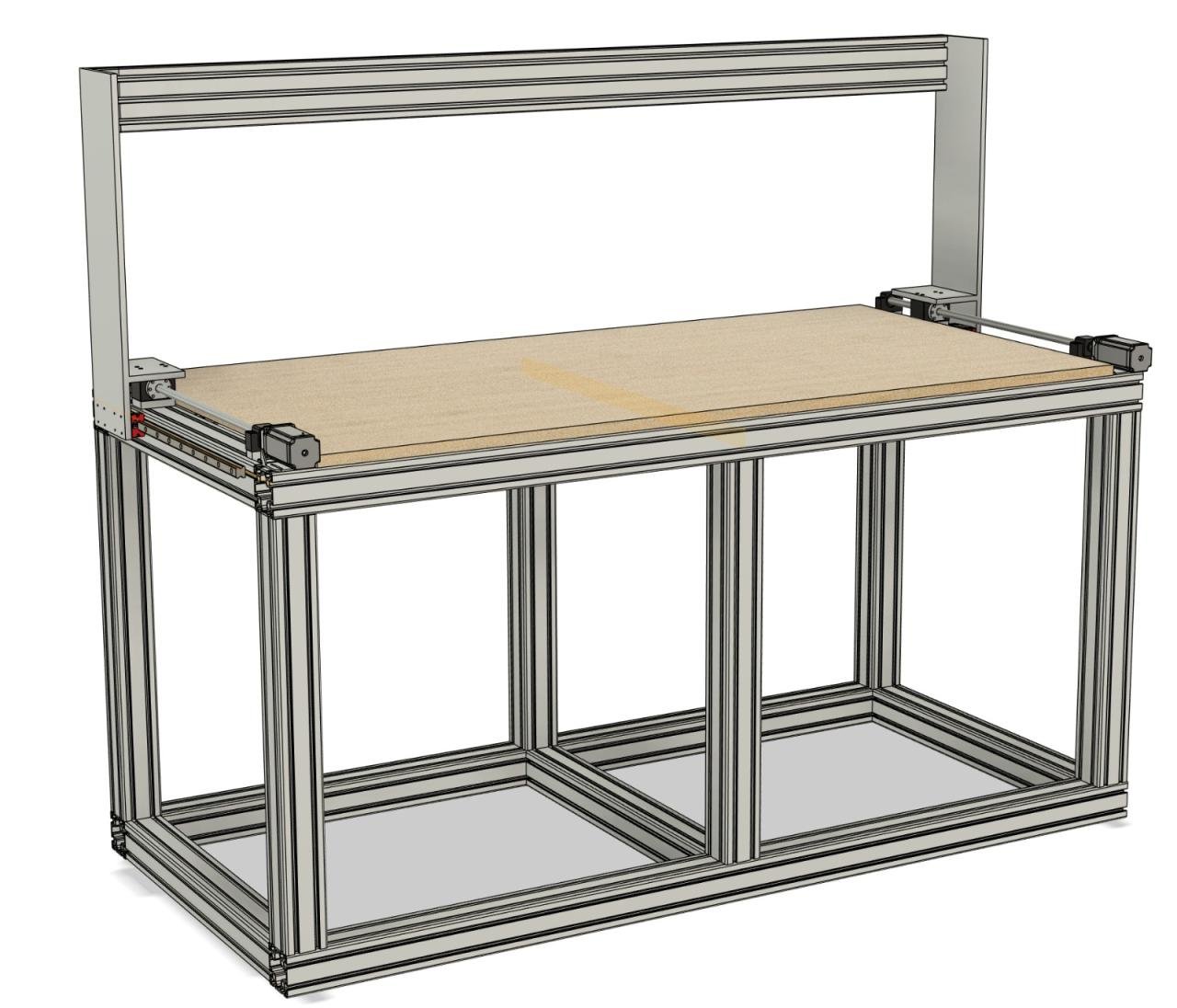
The new frame is built from 80x80 aluminium extrusion:
- worktop of 2000 x 900 mm
- CNC working area of 1600 x 700 x 300 mm
- a drawer compartment
- a compartment for the server rack
The gantry drives all three axes and parks at the back when it is not in use. Then it is simply a workbench. Start a program and the same table is a CNC mill. This gives me more room in the shed and a much larger working area than the old machine.
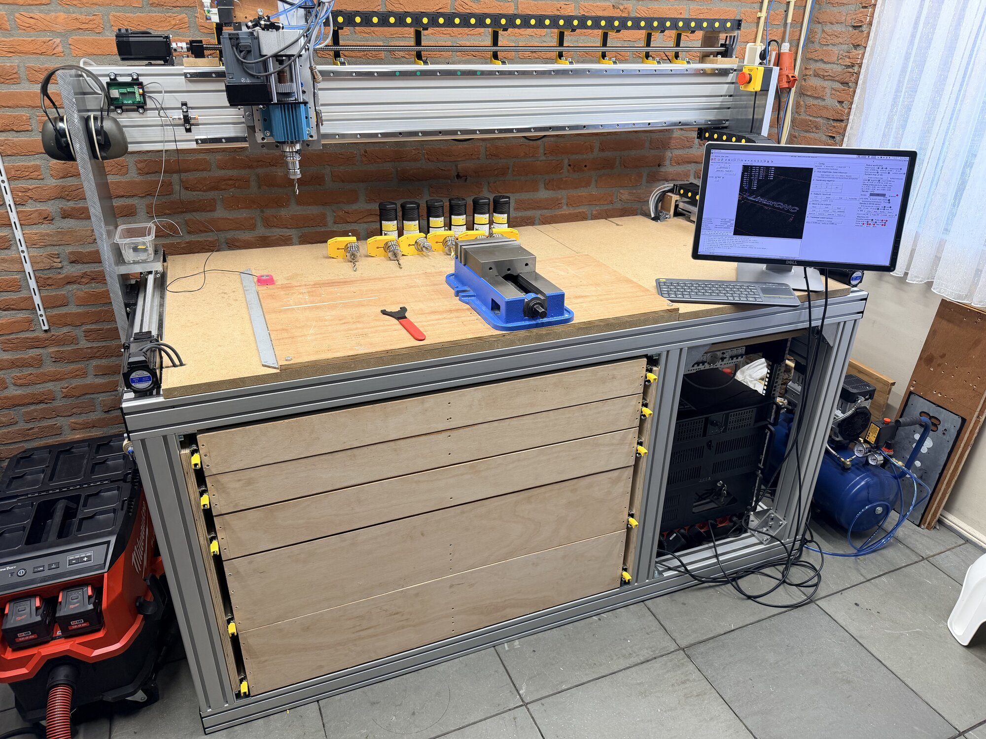
This is how it looks today. The drawers on the left, the server rack with the compressor next to it on the right, and on the worktop the vise, the BT30 tool holders and the screen running LinuxCNC. The gantry is parked at the back, the front part of the worktop is just workbench then.
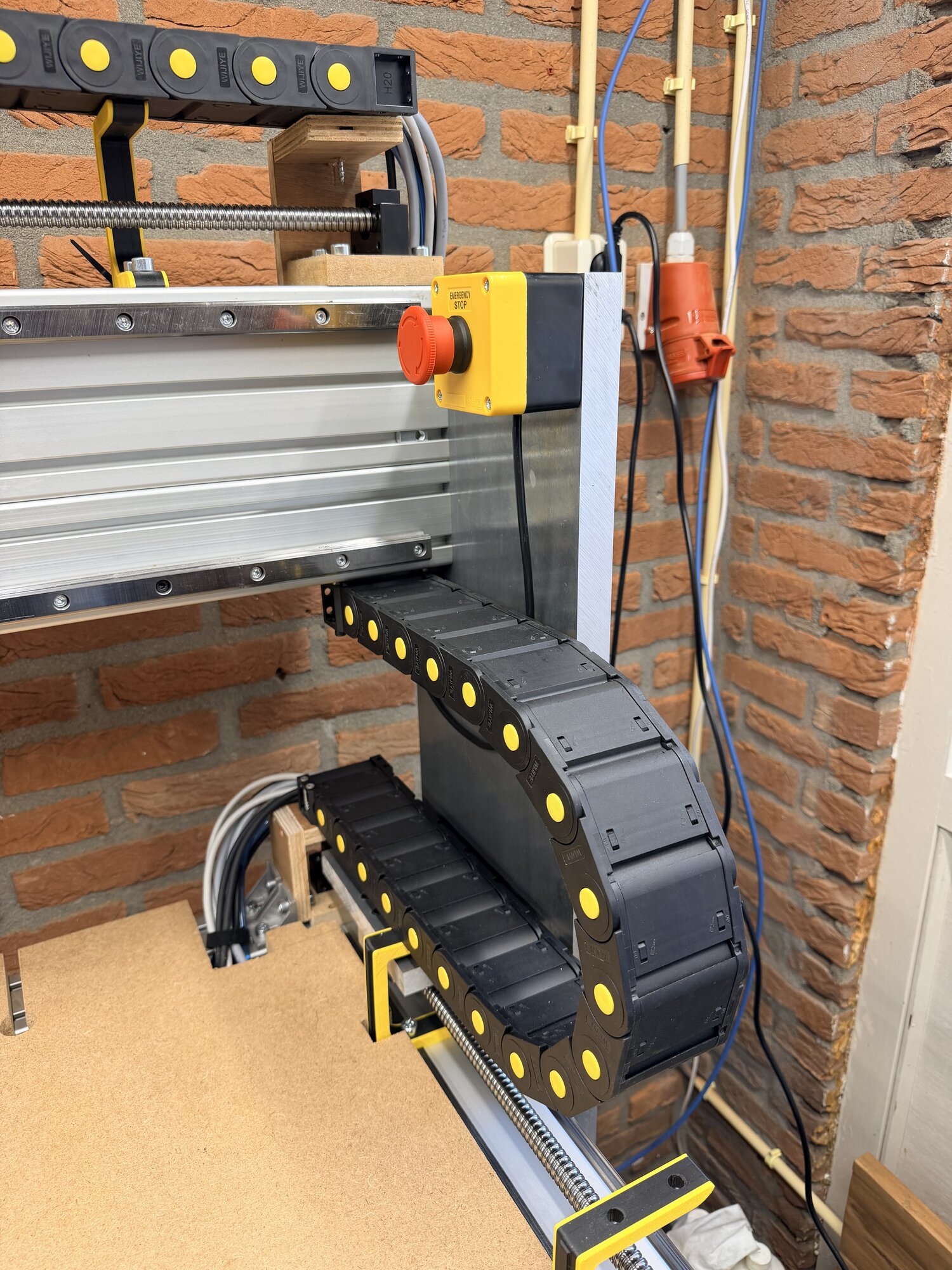
All wiring to the moving parts runs through cable chains. The emergency stop sits on the corner of the gantry, so it is always within reach. Mains power comes in through the CEE connector on the wall.
The spindle carriage
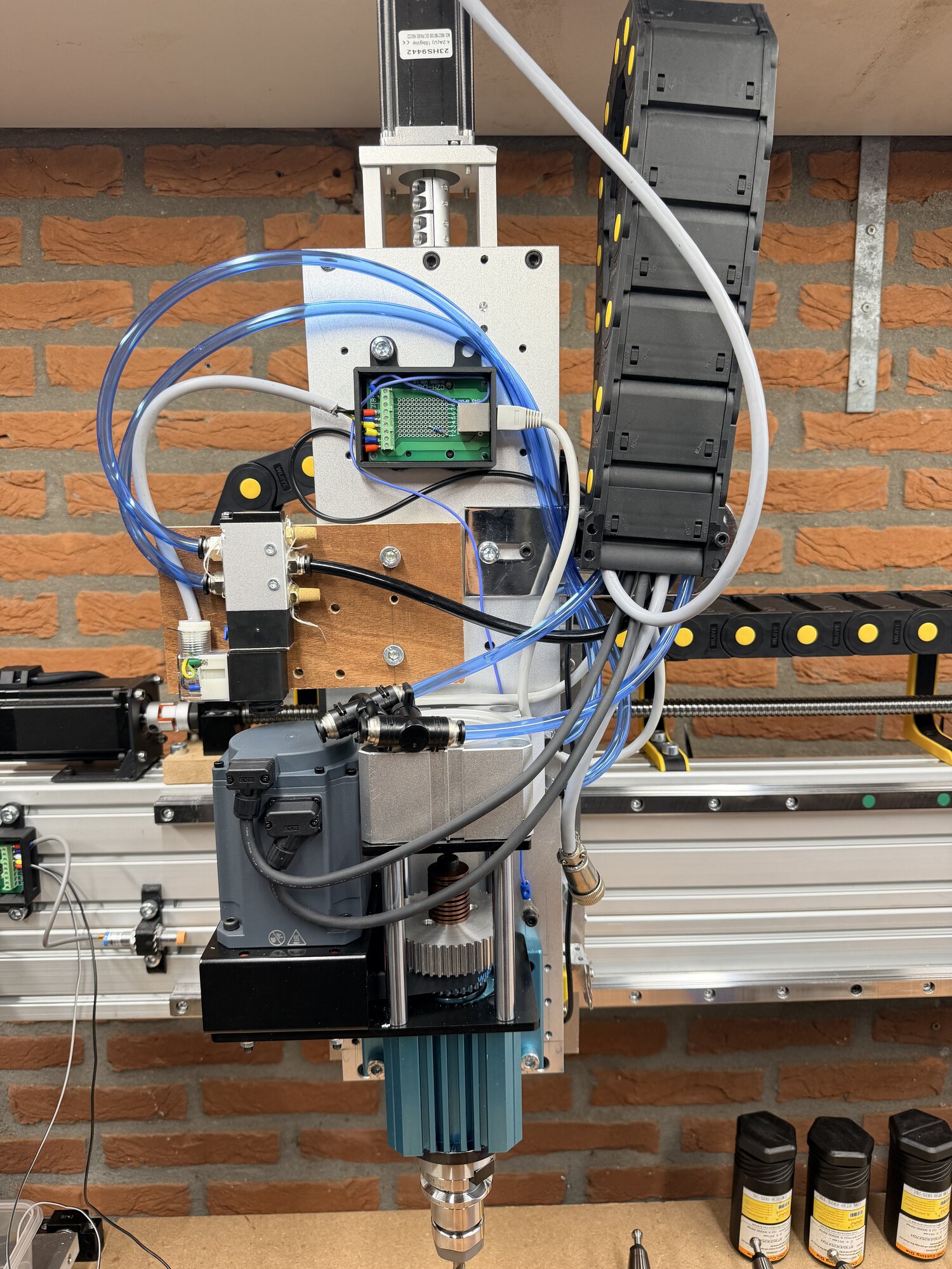
There is more on the carriage than just a mill. At the top sits the stepper motor for the Z axis, below it the pneumatics block with the valves and its own breakout board, and at the bottom the 1.5 kW spindle. The grey motor is a 1000 watt AC servo hanging next to it on a belt.
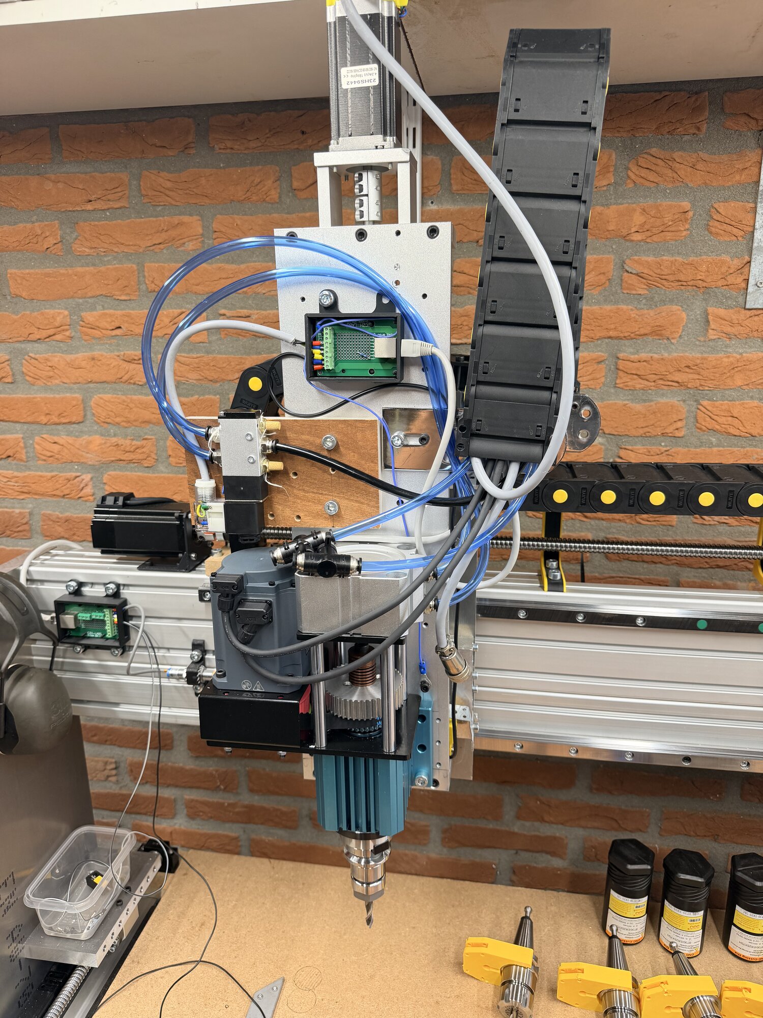
That servo is there for the second head: the spindle can be swapped by hand for a BT30 spindle for low revs, driven by the servo through the belt. This lets the machine change tools automatically. Seven tools in the holder, and the change runs on compressed air with a pneumatic cylinder. This way I can cut heavier at low revs and run a series of operations back to back without changing tools by hand.
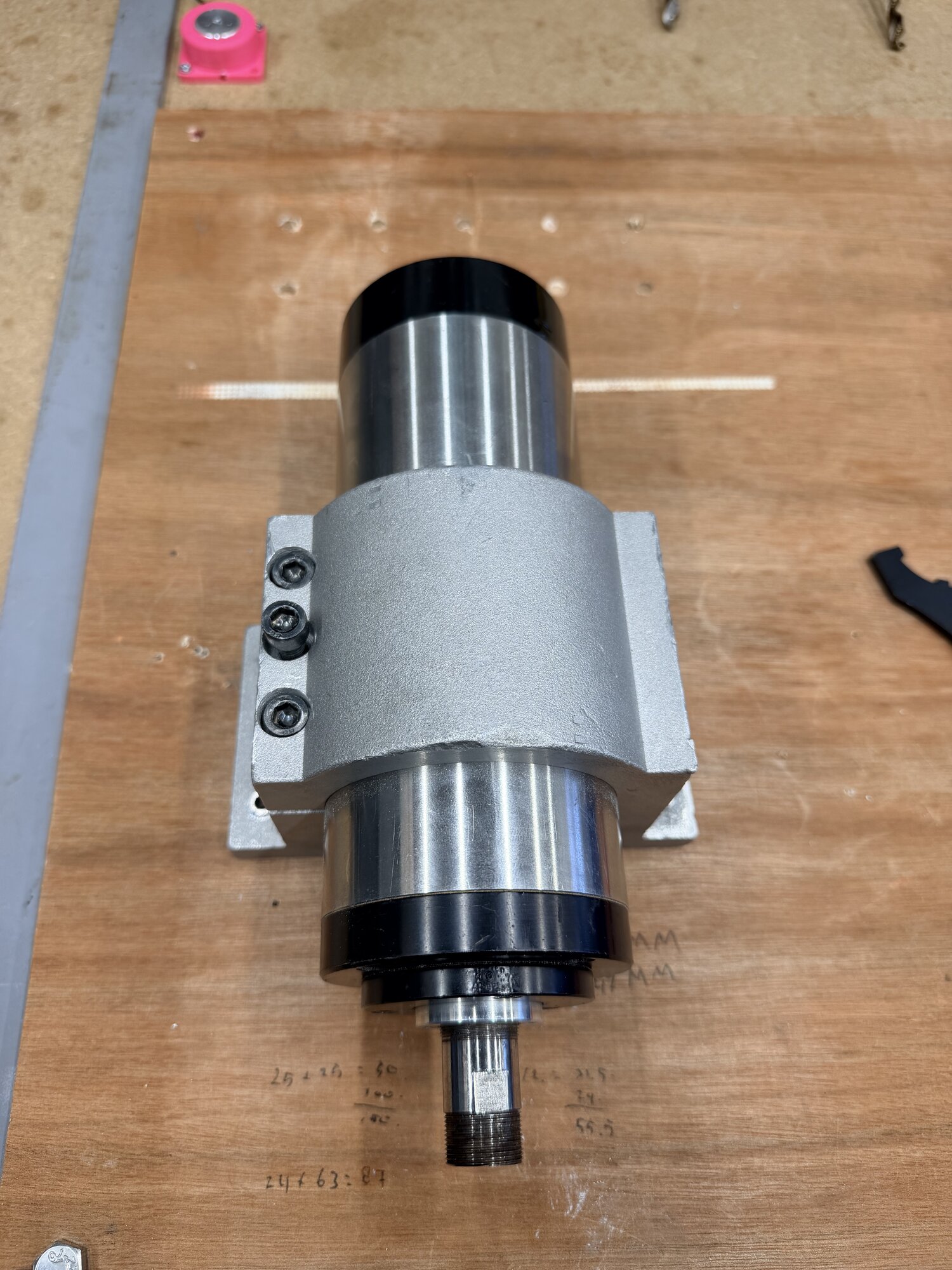
The water-cooled 1.5 kW router spindle loose on the bench. This is the head that comes out when the BT30 goes in. The transmission ratios for the belt are still pencilled on the worktop.
Swapping itself takes a few minutes: close two ball valves, disconnect the VFD cable and the water hoses from the spindle (push to fit, 8 mm, with ball valve), take the spindle out and put the BT30 in. Although the BT30 will simply stay in for now.
LinuxCNC, from 2.7 to 2.9
The old machine ran on LinuxCNC 2.7 with a PCI card and a DB25 breakout. The new one runs LinuxCNC 2.9 and talks to a Mesa 7i76EU over ethernet.
What makes LinuxCNC so interesting: it is not a program but a stack, from hard realtime at the bottom to ordinary desktop software on top. At the bottom runs a Linux kernel with realtime patches (PREEMPT_RT) that guarantees the motion loop really gets its turn every millisecond, even when the desktop is busy. That is the fundamental difference with GRBL-like solutions: there the realtime lives in a microcontroller, here in the PC itself. In that 1 kHz loop everything hard happens: calculating positions, PID controllers, reading and writing I/O.
Above that sits HAL, the Hardware Abstraction Layer, the heart and the most underrated part. HAL is a virtual breadboard: components have pins, and you connect them with wires in text files. Building a machine in LinuxCNC is eighty percent writing HAL wiring. The emergency stop button on this machine is a physical input that runs through an estop latch to the machine enable, and the driver alarms of the axes tap into that same latch through OR gates. One layer up, the G-code interpreter reads the program and the motion planner turns it into a path, without knowing anything about the hardware. And right on top runs the interface with custom panels.
The strength of that stack: every layer can be replaced or extended without touching the rest. The price: you have to know all layers a little before a non-standard machine works. And this machine is quite non-standard.
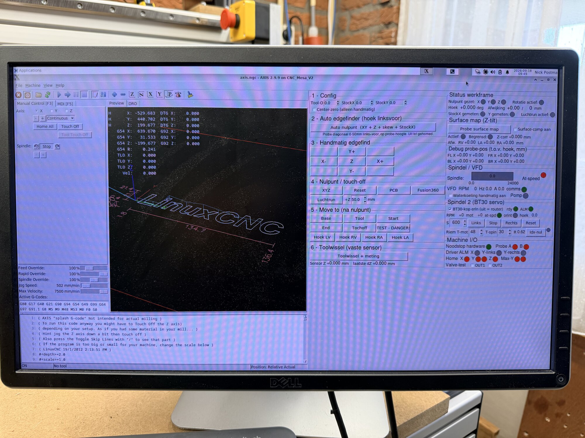
The screen on the table runs AXIS with a custom panel next to it: automatic zero finding with the edge finder, a surface map for Z compensation, tool change with a fixed measuring sensor and its own block for the second spindle. Everything I used to do with loose commands now sits behind a button. Under the hood that is pyvcp XML plus G-code subroutines plus a bit of Python in the AXIS startup, for everything the panel cannot do by itself: tooltips, writing values back, remembering settings across a restart.
How the machine maps onto it
The PC does the control, the Mesa card does the needle precision: step pulses up into the megahertz range, encoder counters and 48 isolated inputs and outputs. Every millisecond one UDP packet goes out and one comes back, and a watchdog on the card freezes all outputs the moment the PC drops out. The closed loop steppers behave like servos: LinuxCNC commands velocity with a PID controller per axis, the card turns it into pulses and the position comes back from the counter.
The two spindles are each connected in their own way. The water-cooled router hangs on a VFD via RS485, with a real at-speed signal from the output frequency of the drive instead of an assumption. The BT30 servo sits on its own stepgen channel, and its encoder feeds back into the Mesa. Because of that LinuxCNC knows the actual spindle position: at-speed from measurement, and soon orienting to the degree, the foundation under the tool changer.
Because the heads are physically swapped, one checkbox in the panel decides where "the spindle" goes. Standard CAM output is routed in HAL to the mounted head, the wrong head is locked out, and a program that calls it anyway is aborted. An rpm clamp prevents an old wood program with S16000 from overspeeding the BT30 cartridge. That sounds excessive, until you consider what happens without it: a VFD without a motor happily reports "at speed" and the machine mills into the workpiece with a standing spindle. One AND gate and an abort signal prevent that.
The nicest thing about HAL: custom realtime components are small. Three of them run here, written in C: a flatness compensation that corrects a measured skew of the workpiece in the Z axis in realtime, a helper to zero the encoder on the index pulse from a panel button, and an angle display. About ten lines of code each.
The electronics
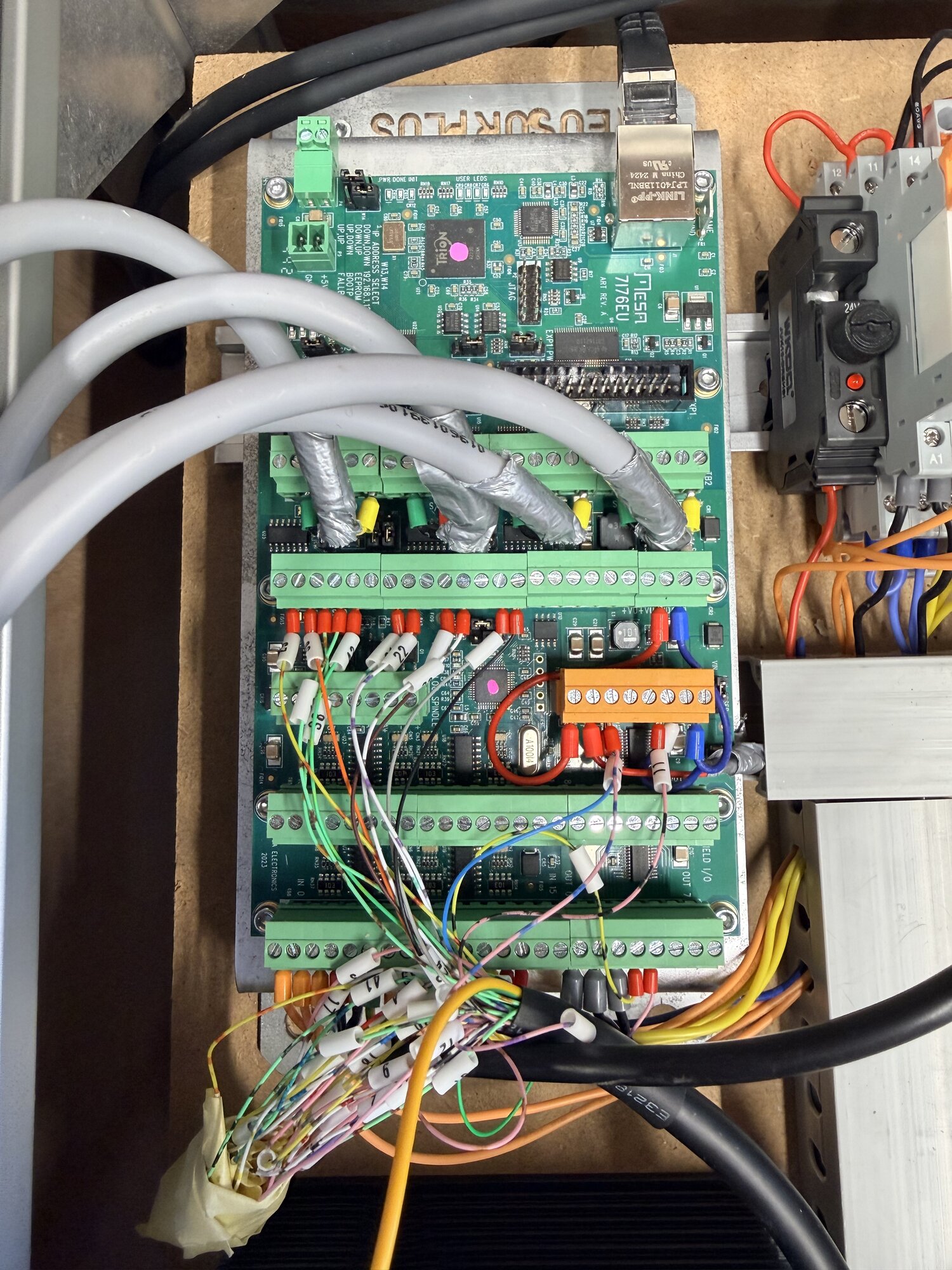
The Mesa 7i76EU in its enclosure, with the field wiring labelled on the terminals. Everything sits on terminals instead of a printer cable.
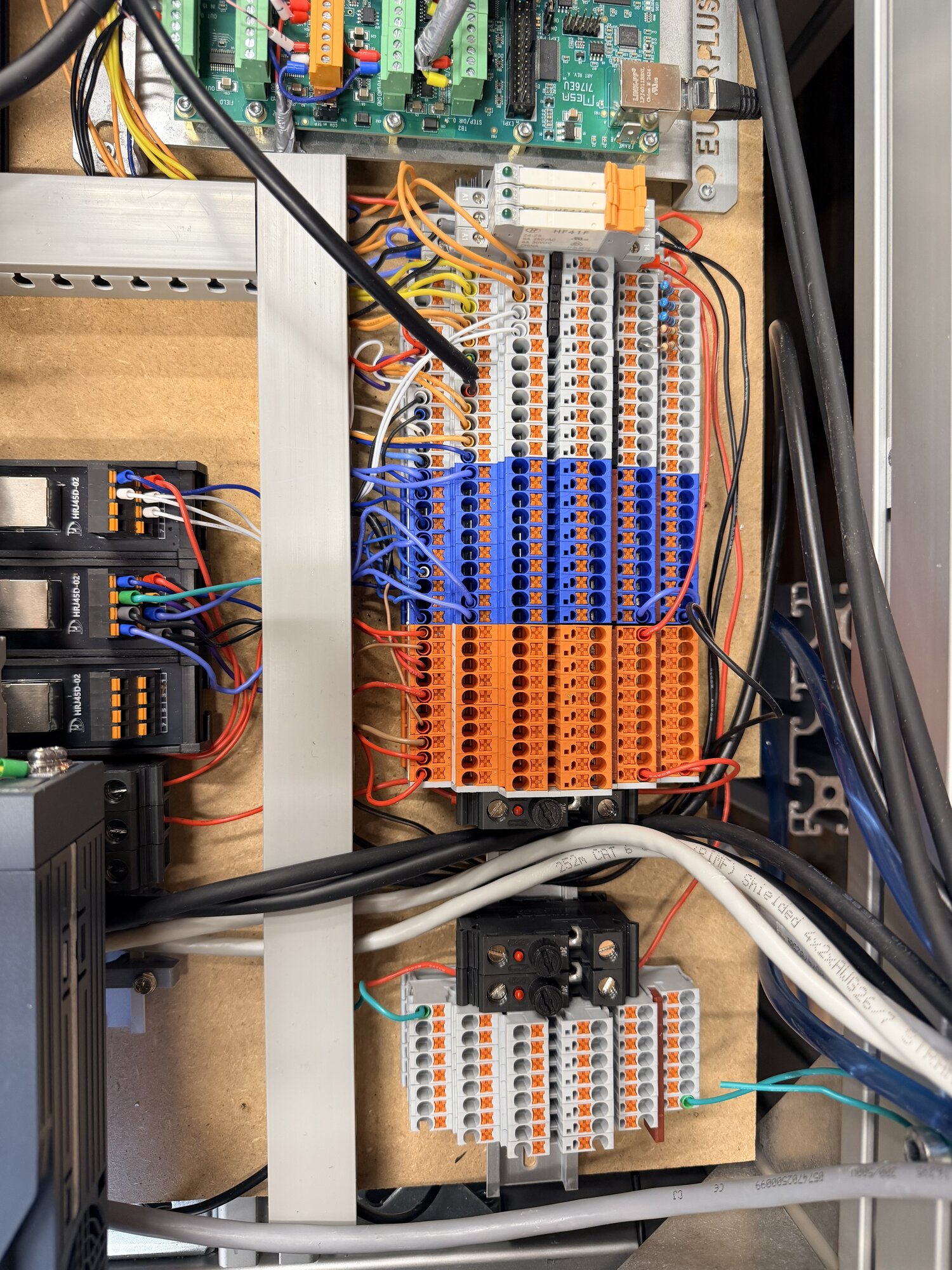
All signals run through terminal blocks, orange and blue separated by function. The RJ45 breakouts on the left take in the signal cables: the proximity sensors, the touch-off and the control of the pneumatic valves, each over its own shielded network cable. With a well thought-out terminal plan, troubleshooting is ten times faster.
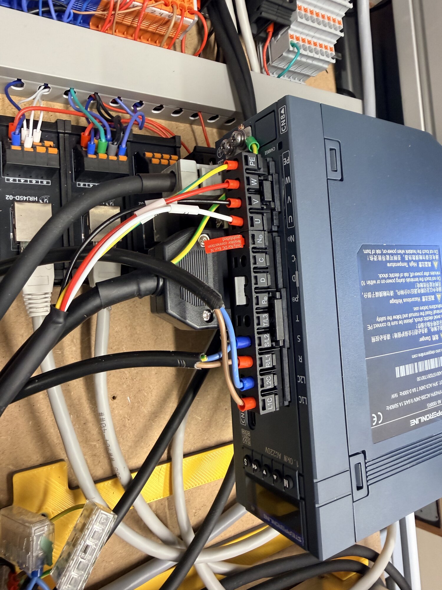
The 1 kW servo drive for the BT30 head, with the motor phases and the encoder on their own connectors. The red marking shows where no braking resistor may go.
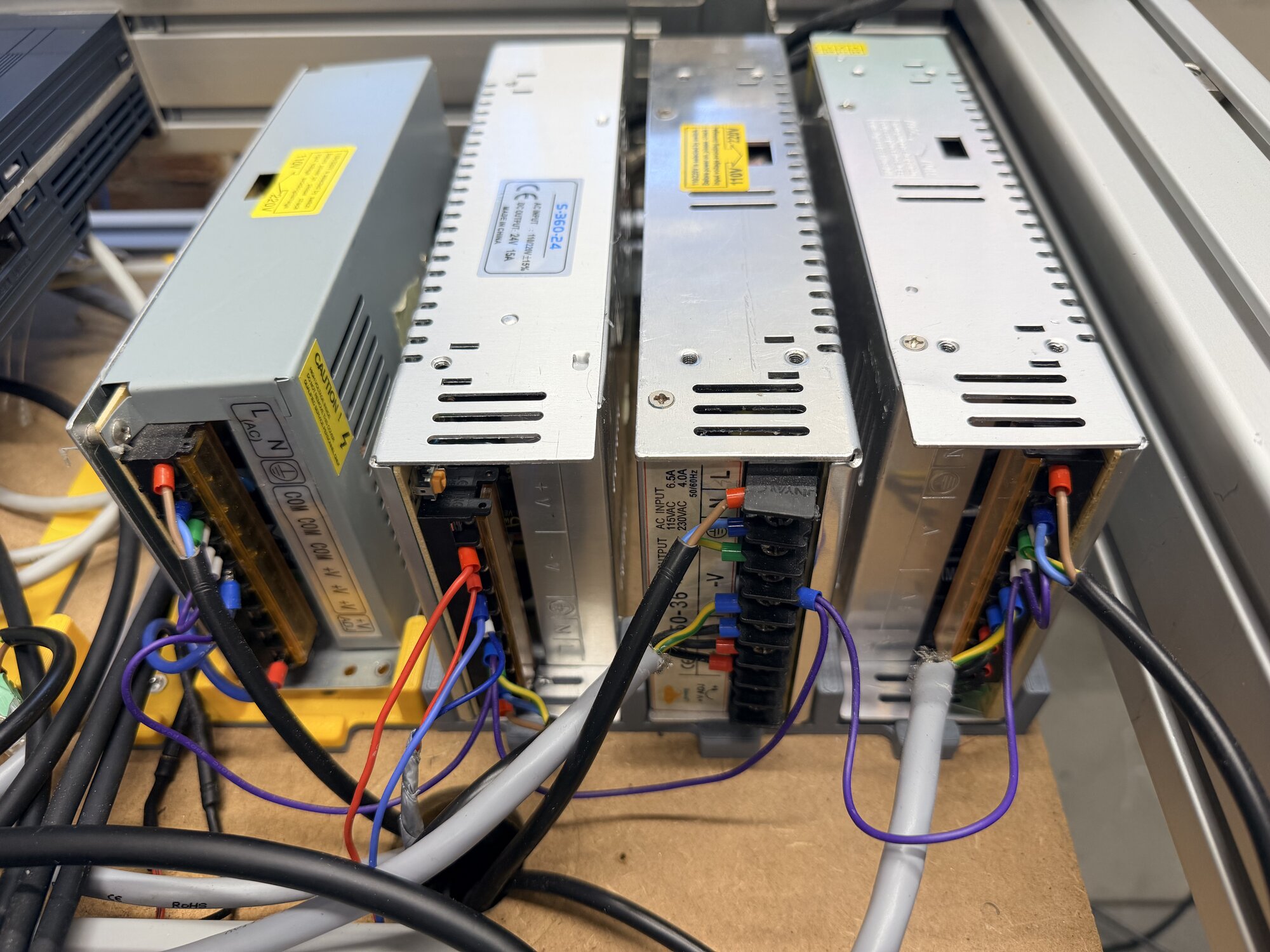
Separate power supplies for the stepper motors, the 24 volt controls and the rest. That way nothing sits on a shared rail interfering with everything else.
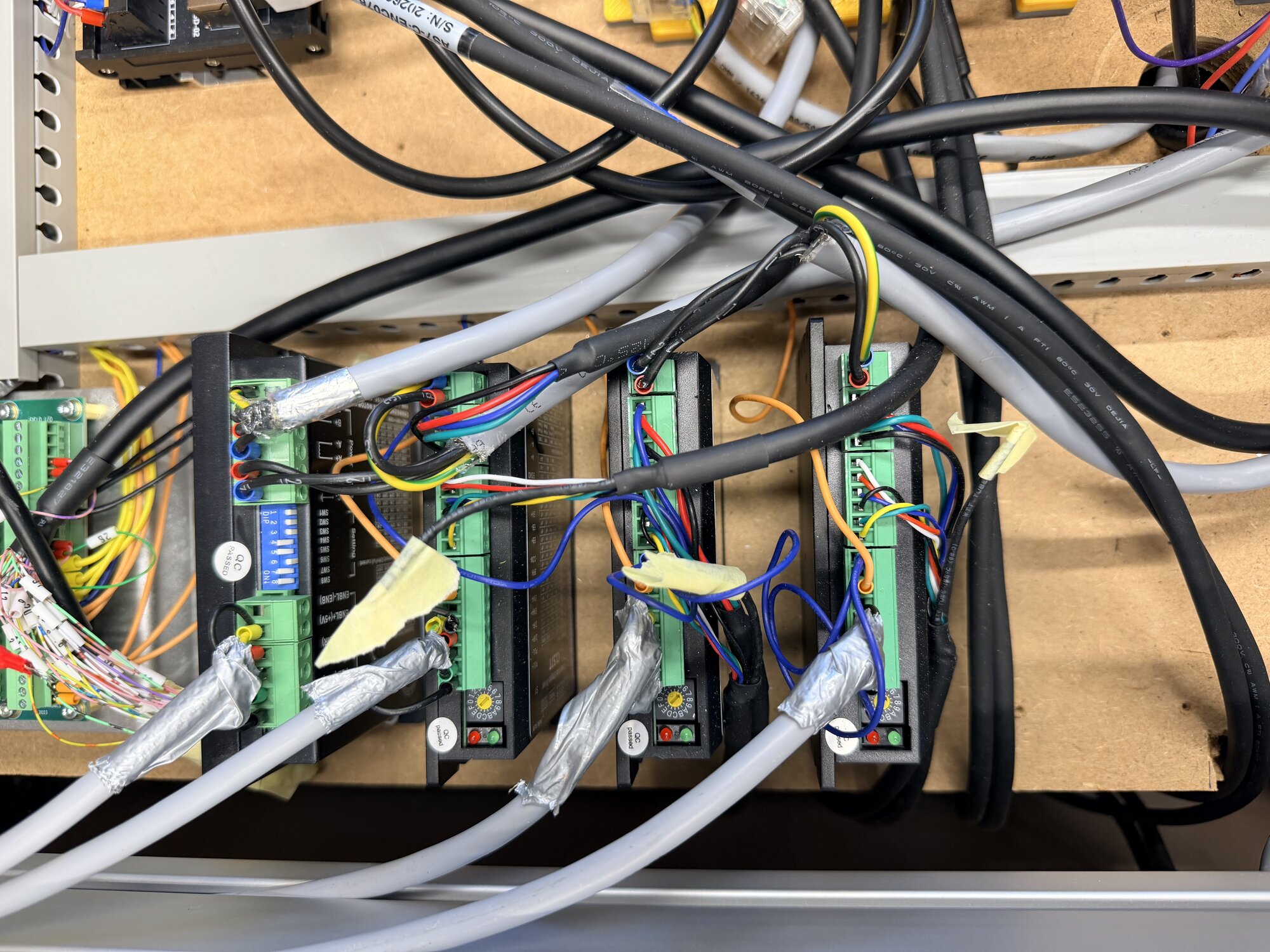
The stepper drivers, each with a shielded motor cable and the shield grounded at a single point. The yellow tape is temporary.
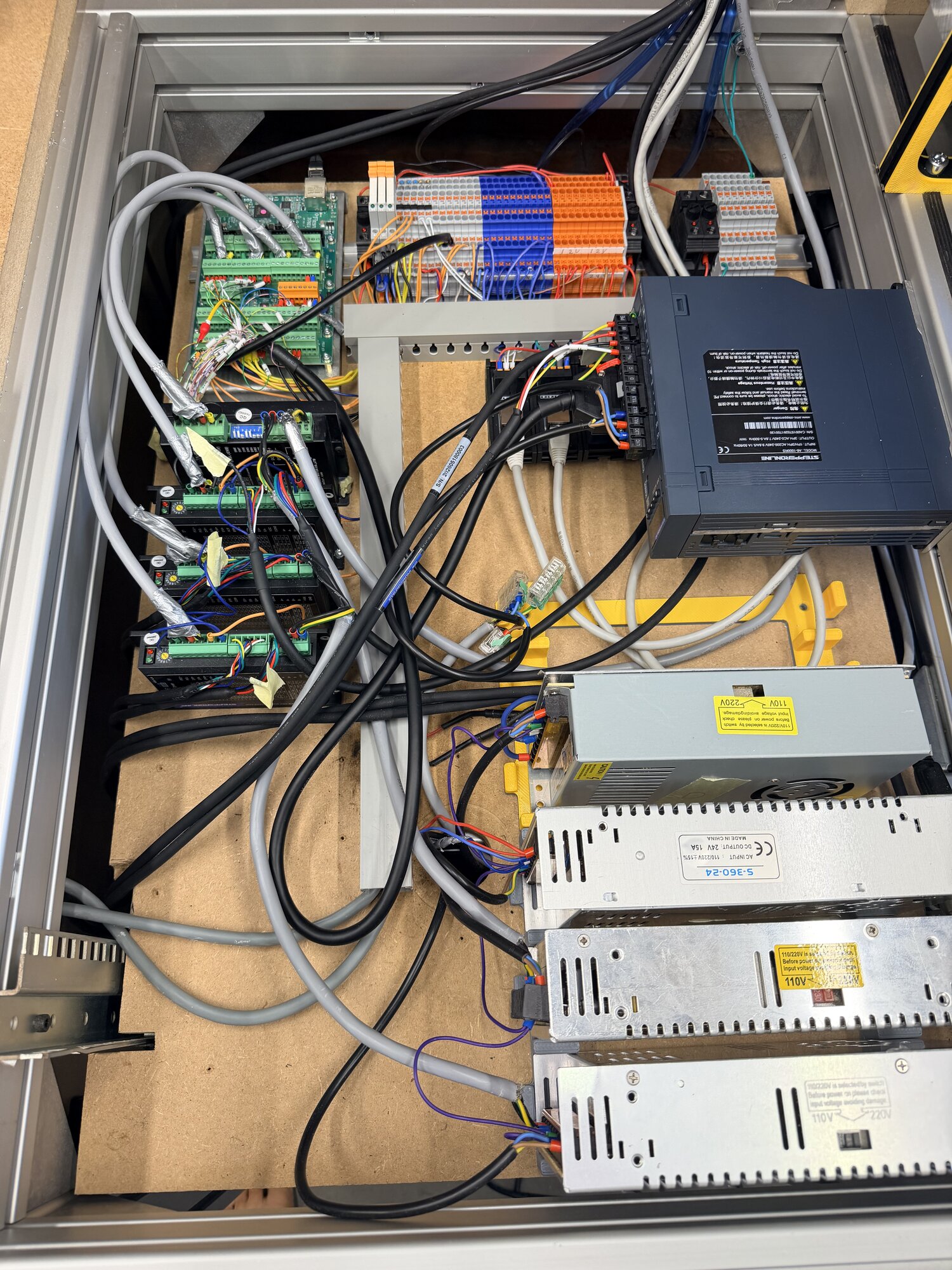
Everything together in the compartment under the worktop: Mesa, terminal blocks, servo drive, power supplies and drivers. I can reach it by pulling open a drawer.
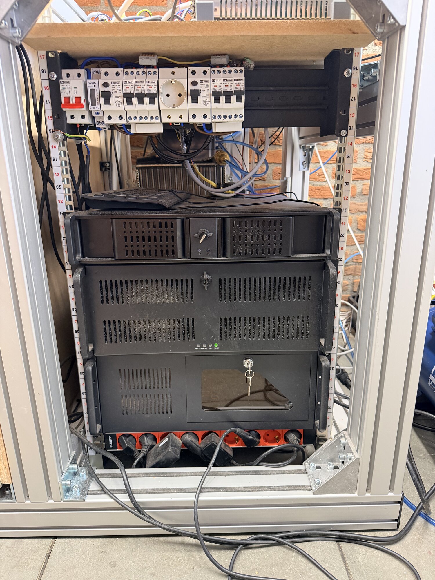
The server rack compartment. At the top its own breaker panel with residual current breakers per function and a kWh meter, below that the rack servers and the PDU. The machine and the servers each have their own circuit.
Two things are not in the photos. Under the electronics shelf hangs the VFD that drives the router spindle, and behind the servers sits a radiator from a Fiat that cools the spindle's cooling water.
What I have learned along the way
LinuxCNC checks almost nothing for you. Swap two encoder wires and the position loop runs the wrong way, the system is fine with it. Everything is possible, so every mistake is possible too. A few lessons from this build:
- Never trust a colour code or a pin number. The motor phases of the closed loop kits turned out to be coupled differently than the datasheet states, encoder colours were counter-intuitive and the factory cable of the servo was labelled per wire but differently from the diagram in the manual. The rule has become: continuity-test at both ends, labels beat colours, and measurements beat everything.
- Fail-safe thinking pays off. An alarm output that only conducts on a fault has a blind spot: drive off or a broken wire reads as healthy. The ready output that conducts when everything is fine is the better guard, because a broken wire then automatically counts as a fault. The same philosophy as NC emergency stops and NC limit switches.
- Signs and scales are half of the tuning. The encoder counted the other way round from the drive direction. That is one minus sign in the config, but it is the minus sign between a position loop that locks in and one that runs away. I wrote a test script that measures both directions itself and prints the diagnosis, and that got it out in a single run.
- A belt drive demands unit discipline. With a 48:30 belt between motor and spindle, everything has to know whether it is talking about the motor or the spindle: S words, rpm displays and the rpm clamp. And the index pulse of the motor is no longer an unambiguous spindle angle, so true spindle orientation for the tool changer will need a reference on the spindle side.
- Startup order is real. Panel values only exist once the interface is running, realtime components run from second zero. Safe defaults on the pins until the panel takes over, and the error messages are gone.
Why LinuxCNC anyway
Everything that sounds difficult above is also the reason this machine can do what it does: two completely different spindles behind one interface, custom probing routines, a flatness compensation that runs along in realtime and a tool changer in the making. There is no closed controller in this price range that allows that. The learning curve is the price of admission. What you get back is a machine of which you understand every wire and every line yourself.
Status
The machine mills (work in progress!). The first tests are done and the basics work: jogging, homing, zero finding, tool measurement. The Z axis still has too much play and you hear that back as chatter in the workpiece. So that is getting a modification.
This project is never really finished, and that is exactly the point. Every extension is another excuse to figure something new out. Questions about the build, the controls or the choices along the way? I would love to hear them.